
Time to explore something outside my comfort zone. Image Processing. I’ve gone through a few geek books during hard to find spare time. There are so many apps in the iOS world that I needed to dig a little deeper to get a better understanding what is under the hood. iOS Programming: The Big Nerd Ranch Guide and Objective-C Programming: The Big Nerd Ranch Guide are good introductions. If you know C/C++ the Objective C book can be read rather quickly. I liked going through the exercises in the iOS programming book (well kindle version) to force me to navigate through the xcode/iOS documentation. My real motivation is to do some image processing and opted to read the OpenCV 2 Computer Vision Application Programming Cookbook.
Power Measurement Revisited
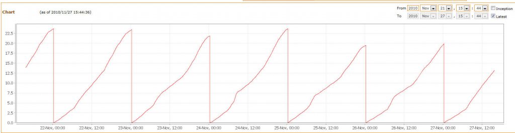
Spot Measurement
I finally got around to tinker with things again and opted to digress from the zigbee standalone mote-like development to revisit the power measurement.
I have three types of sensors to measure currents lying around and decided that given I already wrote the C++ classes and modbus integration for total home energy consumption, I could easily create a spot measurement modbus slave device to monitor specific loads. Note that all my arduinos+zigbee are modbus slave devices and only the mote-like devices shall use a different protocol.
Pin Sleep Xbee with Arduino Host
Making it work.
I got everything to function with a rather messy board setup as shown below.

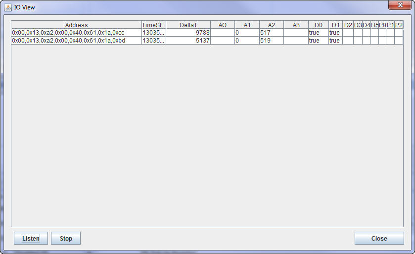
The output from the Arduino shows the delta T between messages received from the end-devices. It is pretty close to the calculated ones. I will change the duration to be 15 minutes later on but for debugging purposes 10s intervals for pin sleep is tolerable.

Pin Sleep Xbee and Documentation Rant
Well everything is wired up and works as planned. Sort of. The journey there was not simple. The datasheets on the xbee around sleep modes covers everything one needs to set that up. The problem is that it is not a first pass approach for a newbie. I had to scratch my head a few times.
Continue reading
Sleep Mode – Timer Setup
Upgraded to wordpress 3.2. Quite painless.
Setting up the Timer
I received my components from digikey to finish the mesh based data collection prototyping. One of the components is the LTC6991 timer chip. I never soldered surface mount devices before so I did my share of reading up on it. Mine turned out functional but not the best looking. Hats off to those who make it look easy. The IC is TSOT-23 and I purchased a breadboard friendly board to solder it to.
Sleep Mode
I opted for hardware driven sleep mode (SM=1) in the XBee. I felt that that cyclic sleep mode (SM=4) to be a pain to setup. I felt that that keeping the XBee asleep for extended durations, the device would be MIA from host. With a hardware based sleep, I could use a swith to to force it awake, configure remotely with the software tool I wrote, flick the switch back to the timer based sleep. Simple in my mind.
Estimated Battery Lifetime
The resulting solution must run on batteries (coin type ideally) and I wanted to get a sense of the operating time between battery changes. The spreadsheet utilized the cells in red as variables. Assuming a wake up during of 30ms and sending a sample every 100 seconds, I can run for an acceptable amount of time. The problem occurs when I include a 78L33 level converter, 555 timer, and a sample sensor like the LM35. I will need to look into this as this might be a show stopper on the battery only constraint.
XBee API Mode
So now that I have the latest firmware installed on a coordinator, router, and 2 end devices all set up for PAN ID=47, it is time to write some software to experiment with the other settings. I am not a fan of the X-CTU software and decided to write a simple test application to configure my devices. The vision is to use X-CTU software to upgrade the firmware, set the API mode, and Pan ID. After that, the rest of the provisioning would occur from the software I wrote to configure the devices. I want to commission new XBees for the “field” with just a few clicks of a mouse. I tend to forget things after a while so tacit information should be captured in the software.
I used the Java API for Digi XBee/XBee and jformdesigner within Eclipse to write a simple application as shown below. The software I wrote allows me to discover devices and drill down a given device to change parameters.
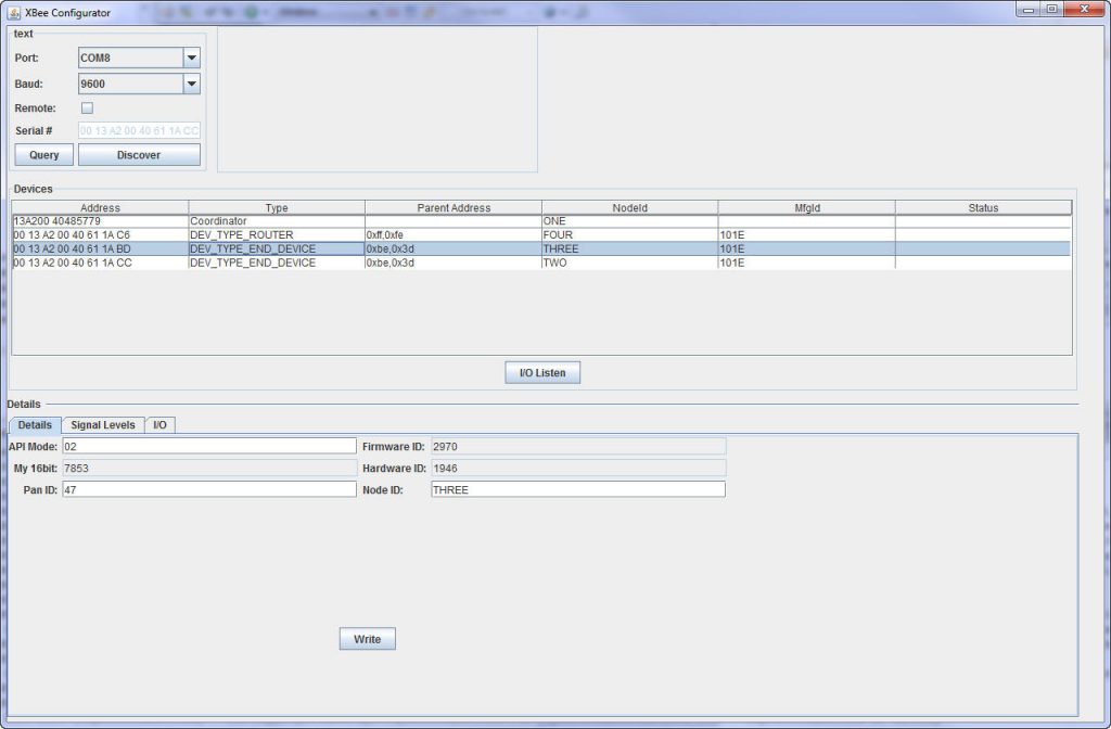
I also needed a way for me to experiment with I/O settings and sampling modes as well. This allows me to configure a device and poll the data values. The XBee sheet I use is found here.
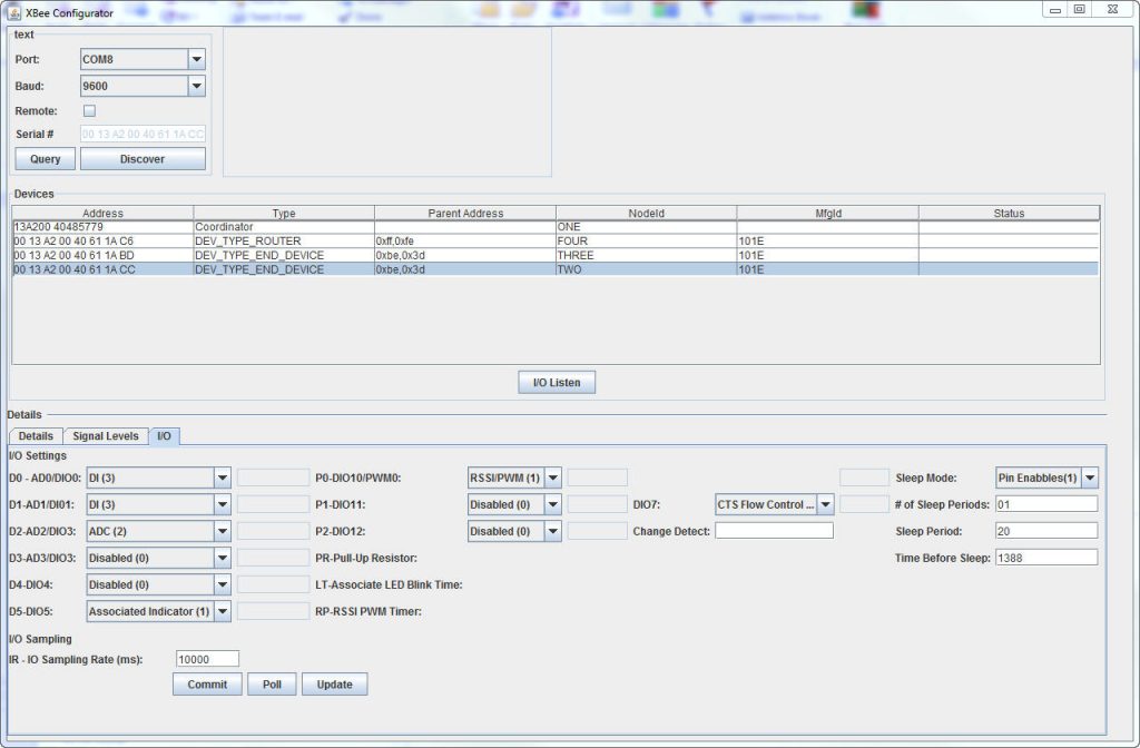
In the end, the goal is to have the end device send their values after a sleep time so I added a listen that posts IO from end devices along with deltaTs between samples.
Time to experiment.
New Project – Xbee Mesh Network and Data Collection
I needed a project to dabble and distract me in a constructive manner. The goal for this project is to build a low power data collection network to sample slow changing analog data such as temperature, ambient lighting, among other things. The constraint given was to use XBee Series 2, run in API mode, and operate on batteries.
I purchased 5 XBee Series 2s to experiment with. I used X-CTU software to configure the Xbee chips as per the last project I did. The difference this time is I did not want to use AT mode but API mode to give me more control over XBee interactions from the Arduino host software. The project context is as shown below.

Finished–Good Enough
Wiring to the Power Main
I finally got around to put in the current transformers (CTs) in the panel last weekend. I had an electrician come and pull the meter out so I could install them. If you are wondering, I got permission from the utility company to do so. In hind-sight, I should have purchased split core transformers and just clip them on.
I can’t say much more about this, as it was quite a no brainer to do. This was the first time I tested my Arduino with more than 13 amps and my only concern was if I was off in my scaling. Using commercial grade CT provide linear operation in the range I’m interested.

I took a utilitarian view in packaging the Ardiuno and circuitry and ended up using a dead router enclosure to host the solution. With limited tools, I cut out a place for the LCD and xbee radio. It works and is out of the way so it met my simple requirements.

Collecting the Data
I can collect power related information as shown below and log it over time for trending purposes. I can also collect reactive and apparent power but for power factor tells me the story at a glance. As stated in an earlier post, I used Mango to do all that. I was posting stuff on Pachube and exceeded the posts allowed for free so I disabled it. I will revisit this later as this is not a high priority.
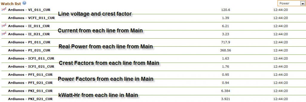
Also trended it the cumulative lbs of CO2 that is spewed out based on my consumption. I reset the counter at midnight every night. I do the same with costs and kWatt-hr consumption.
If I had to Start Over
I would have wired and programmed the solution to handle updates over the xbee. I settled for plugging the laptop in the device and load changes that way.
Next Project
I would like to stuff the server side software in a fanless PC like an ARTiGO. I must admit this stuff is boring and prefer to venture into more math/physic problems. Migrating the server side software is not really a project and more something I have to do as one of my desktop PCs is doing the data collection.
The next project is to measure the temperature in different rooms and just use the XBee and a temperature transmitter. I also want to sense the on/off of key appliances as well over XBee. Alas, I don’t have the cycles to work on this as this is a part-time hobby.
So far I slapped together an Arduiono with XBee and transmit the temperature over modbus as illustrated in the diagram below.

The power monitoring Arduino has a slave ID of 2 and the temperature Arduino of 3. Using an Arduino to collect a temperature is overkill and is why I want to change it to be low power over a mesh network around the house. I may have a data concentrator over modbus to bridge the mesh with the host and something like the diagram below. Who knows.
