Relatively Easy
I’ve been busy with work and never have the time to get back to this project. Anyway, I penciled in a few hours to wire up the xBee transmitter/receiver to the arduino. The xBee explorer is a time saver. What I wanted to do is to program the arduino over wireless as well. Given that time is limited, I opted to just send data over wireless to simplify connectivity.
The xBee explorer had 4 connection points that made it easy to hookup:
- +5 to arduino +5
- gnd to arduino ground
- dout to rx (pin 1 of ardiuino)
- din to tx (pint 2 of arduino)
That is pretty all that is required to wire up the xbee. The explorer takes care of the 5v to 3.3v level shifting. Remember I am using the Duemilanove as the reference board. Note that you can’t plug in the USB in the Duemilanove and xBee in the explorer at the same time. The two will conflict with each other. This is rather trivial to hook up so no wiring diagram other than pin connection mapping is provided.
On the host side, I used the USB explorer which is basically leads to a plug and play model which I like. Rather than regurgitate xBee configuration, I found that it is well explained here. (Xbee Configuration tutorial) I tweaked the PAN, Baud rate, and type. I made the host a coordinator and the slave device a routing type. Again, explained well in the tutorial.
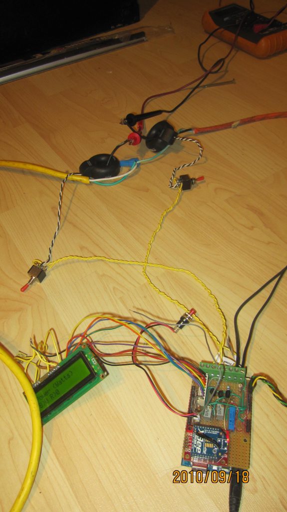
Just like the other parts of this project, I found soldering and wiring it up the hardest. I used left over wire wrap wires (I think the stuff is 20 years old) to connect things. I don’t wire wrap them and still solder. I like it because it is not tot bulky. It does break easy though. Anyway, I have a renewed appreciation for those who package hardware. Although mine works, only a mother could love the way it looks. Alas, it is for my own use so prototype mode is good enough.

Current Transformer Revisited
I revisited the current transformer wiring in the context of safety. Rather than use terminal blocks, I should have used simple audio jacks to simplify the wiring. Either way, there was a safety issue that loomed in the back of my head and I wanted to address it before wiring the sensors to the power mains. The secondary in an open circuit mode of a transformer (not connected to anything) can reach a high voltage and should it come in contact to a person, guess who is going to be the resistor for that voltage to close the circuit. You. It does not take much to kill you.
What I did was add a switch that shunts (shorts) the secondary of the transformer that I flip to “field work mode” before handling the terminals. This is not like shorting a 120 AC line. The voltage on the secondary is the function of the reflection of the impedance on the primary. This can get mathematical so I will spare the math. Suffice it to say that shunting the secondary won’t hurt the current transformer and will add another level of safety.